Circuits often contain elements of resistance, inductance, and
capacitance. In an inductive AC circuit, current lags voltage by
90 degrees. In a AC capacitive circuit, current leads voltage by
90 degrees. It can be seen that inductance and capacitance
are 180 degrees apart. Since they are 180 degrees apart, one
element will cancel out all or part of the other element.
An AC circuit is
• Resistive if XL and XC are equal
• Inductive if XL is greater than XC
• Capacitive if XC is greater than XL
Calculating Total Impedance in a Series R-L-C Circuit The following formula is used to calculate total impedance of a circuit containing resistance, capacitance, and inductance
In the case where inductive reactance is greater than capacitive
reactance, subtracting XC from XL results in a positive number.
The positive phase angle is an indicator that the net circuit
reactance is inductive, and current lags voltage In the case where capacitive reactance is greater than inductive reactance, subtracting XC from XL results in a negative number The negative phase angle is an indicator that the net circuit reactance is capacitive and current leads voltage. In either case the value squared will result in positive number
Calculating Reactance and Impedance in a Series R-L-C Circuit In the following 120 volt, 60 hertz circuit, resistance is 1000 Ω, inductance is 5 mh, and capacitance is 2 μF. To calculate total impedance, first calculate the value of XL and XC, then impedance can be calculated
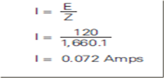
Calculating Circuit Current in a Series R-L-C Circuit
Ohm’s Law can be applied to calculate total circuit current
Parallel R-L-C Circuit Total impedance (Zt) can be calculated in a parallel R-L-C circuit if values of resistance and reactance are known. One method of calculating impedance involves first calculating total current then using the following formula
Zt = Et / It
Total current is the vector sum of current flowing through the
resistance plus, the difference between inductive current and
capacitive current. This is expressed in the following formula
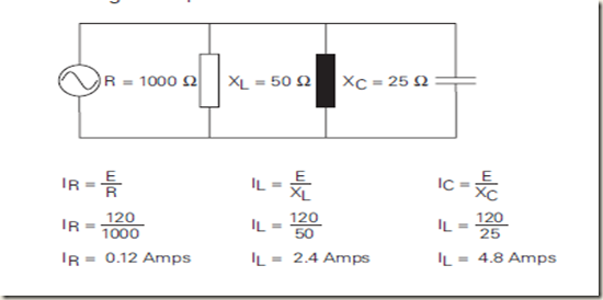
In the following 120 volt, 60 hertz circuit, capacitive reactance
has been calculated to be 25 Ω and inductive reactance
50 Ω. Resistance is 1000 Ω. A simple application of Ohm’s Law
will find the branch currents. Remember, voltage is constant
throughout a parallel circuit.
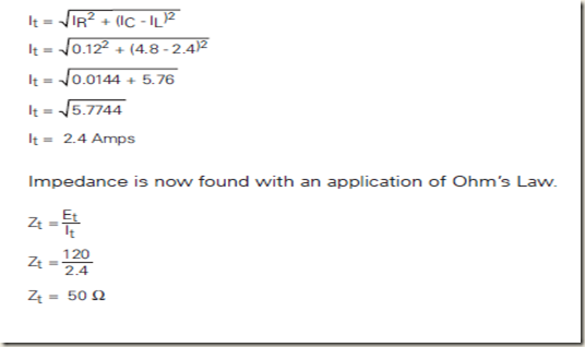
Once the branch currents are known, total current can be calculated.
Impedance is now found with an application of Ohm’s Law.


No comments:
Post a Comment