DC Series Circuit
A series circuit is formed when any number of resistors are connected end-to-end so that there is only one path for current to flow. The resistors can be actual resistors or other devices that have resistance. The following illustration shows four resistors connected end-to-end. There is one path of current flow from the negative terminal of the battery through R4, R3 R2, R1 returning to the positive terminal
Formula for Series Resistance
The values of resistance add in a series circuit. If a 4 Ω resistor is placed in series with a 6 Ω resistor, the total value will be 10 Ω. This is true when other types of resistive devices are placed in series. The mathematical formula for resistance in series is
R t = R1 + R2 + R3 + R4 + R5
Rt = R1 + R2 + R3 + R4 + R5
Rt = 11,000 + 2,000 + 2,000 + 100 + 1,000
Rt = 16,100 Ω
Current in a Series Circuit
The equation for total resistance in a series circuit allows us to simplify a circuit. Using Ohm’s Law, the value of current can be calculated. Current is the same anywhere it is measured in a series circuit.
Voltage in a Series Circuit
Voltage can be measured across each of the resistors in a circuit. The voltage across a resistor is referred to as a voltage drop. A German physicist, Kirchhoff, formulated a law which states the sum of the voltage drops across the resistances of a closed circuit equals the total voltage applied to the circuit. In the following illustration, four equal value resistors of 1.5 Ω each have been placed in series with a 12 volt battery. Ohm’s Law can be applied to show that each resistor will “drop” an equal amount of voltage
First, solve for total resistance
Rt = R1 + R2 + R3 + R4
Rt = 1.5 + 1.5 + 1.5 + 1.5
Rt = 6 Ω
I = E / R = 12/ 6 =2
I = 2 Amps
E = I x R
E = 2 x 1.5
E = 3 Volts
Voltage Division in a Series Circuit
It is often desirable to use a voltage potential that is lower than the supply voltage. To do this, a voltage divider, similar to the one illustrated, can be used. The battery represents Ein which in this case is 50 volts. The desired voltage is represented by Eout which mathematically works out to be 40 volts. To calculate this voltage, first solve for total resistance
Rt = R1 + R2
Rt = 5 + 20
Rt = 25 Ω
I = Ein / Rt = 50/ 25 =2 amp
Eout = I x R2
Eout = 2 x 20
Eout = 40 Volts
Resistance in a Parallel Circuit
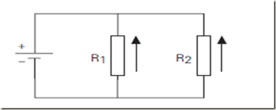
A parallel circuit is formed when two or more resistances are placed in a circuit side-by-side so that current can flow through more than one path. The illustration shows two resistors placed side-by-side. There are two paths of current flow. One path is from the negative terminal of the battery through R1 returning to the positive terminal. The second path is from the negative terminal of the battery through R2 returning to the positive terminal of the battery
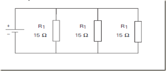
Formula for Equal Value Resistors in a Parallel Circuit To determine the total resistance when resistors are of equal value in a parallel circuit, use the following formula
Rt = Value of any one Resistor / Number of Resistors
In the following illustration there are three 15 Ω resistors. The total resistance is
Rt = Value of any one Resistor / Number of Resistors
Rt = 15 / 3 = 5 Ω
Formula for Unequal Resistors in a Parallel Circuit
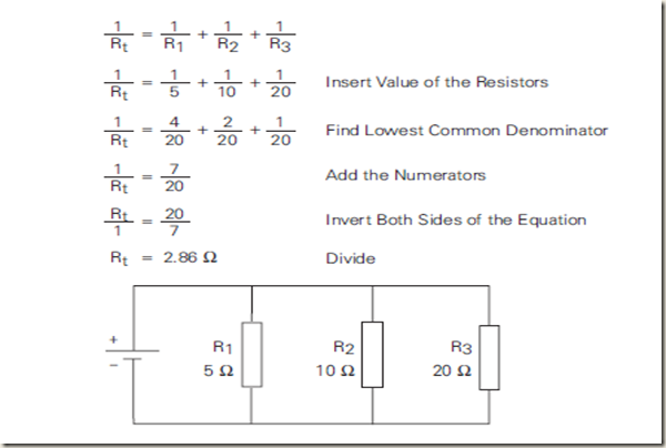
There are two formulas to determine total resistance for unequal value resistors in a parallel circuit. The first formula is used when there are three or more resistors. The formula can be extended for any number of resistors
In the following illustration there are three resistors, each of different value. The total resistance is
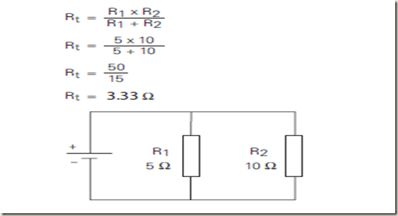
The second formula is used when there are only two resistors
In the following illustration there are two resistors, each of different value. The total resistance is
Voltage in a Parallel Circuit
When resistors are placed in parallel across a voltage source the voltage is the same across each resistor. In the following illustration three resistors are placed in parallel across a 12 volt battery. Each resistor has 12 volts available to it
Total current in a parallel circuit is equal to the sum of the current in each branch. The following formula applies to current in a parallel circuit
It = I1 + I2 + I3
Current Flow with Equal Value Resistors in a Parallel Circuit
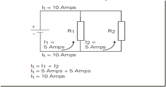
When equal resistances are placed in a parallel circuit opposition to current flow is the same in each branch. In the following circuit R1 and R2 are of equal value. If total current (It) is 10 amps, then 5 amps would flow through R1 and 5 amps would flow through R2.
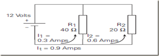
When unequal value resistors are placed in a parallel circuit opposition to current flow is not the same in every circuit branch. Current is greater through the path of least resistance.In the following circuit R1 is 40 Ω and R2 is 20 Ω. Small values of resistance means less opposition to current flow. More current will flow through R2 than R1
Using Ohm’s Law, the total current for each circuit can be calculated
I 1 = E /R 1 = 120 / 40 = 3 A
I 2 = E / R 2 = 120 / 20 = 6 A
It = I1 + I2 =3 Amps + 6 Amps = 9 A





No comments:
Post a Comment